🔧 Hardware Setup Guide
Complete guide to replicate the WLeaks water leak detection system
System Overview
The WLeaks system uses three YF-S201 flow meters positioned at entry, middle, and exit points of a water circuit. An Arduino Mega 2560 reads pulse signals from the sensors and communicates with a Node.js server over USB serial. When a leak or blockage is detected, the Arduino triggers a relay module to shut off the water pump.
Why 3 sensors? By comparing flow rates at multiple points, we can detect where
issues occur. If sensor 1 reads high but sensor 2 reads low, there's a leak between them.
Required Components
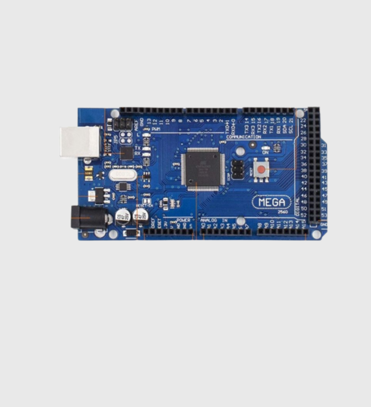
Arduino Mega 2560
- ATmega2560 microcontroller
- 54 digital I/O pins
- 16 analog inputs
- USB serial communication
- Operating voltage: 5V
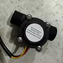
YF-S201 Flow Meter (×3)
- Hall-effect sensor
- Flow range: 1-30 L/min
- Pulse frequency: F = 7.5 × Q
- Working voltage: 5-18V DC
- G1/2" thread connection
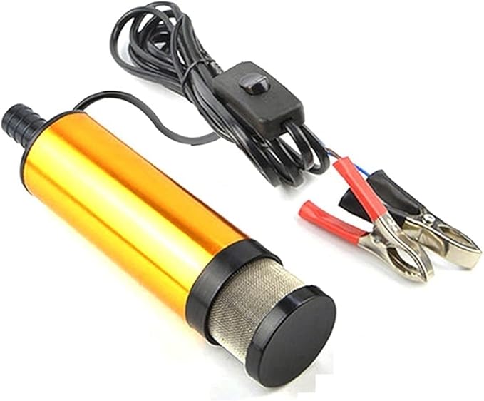
12V DC Submersible Pump
- Voltage: 12V DC
- Current: 1.8A @ 12V
- Flow rate: 12 L/min
- Motor speed: 8500 RPM
- Tubing: 16mm diameter
- Material: Stainless steel
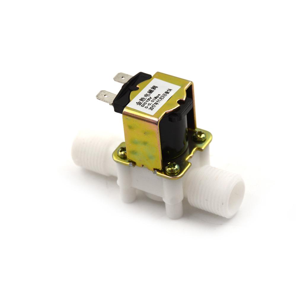
ZE-4F180 Solenoid Valve
- Voltage: 12V DC
- Normally closed (NC)
- Thread: G1/2"
- Max pressure: 0.8 MPa
- Response time: <0.15s
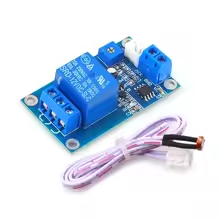
5V Relay Module
- Input: 5V DC
- Optocoupler isolated
- Rating: 10A/250VAC
- Trigger: Active LOW
- LED status indicator
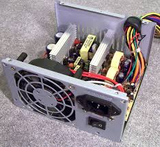
Modified ATX PSU
- 12V rail: Pump power
- 5V rail: Logic circuits
- Green wire to GND: Always ON
- Repurposed from old PC
Additional Materials
- LM2596 DC-DC Buck Converter (adjustable, 3A max)
- 16mm silicone tubing (food-grade)
- Jumper wires (male-to-male, male-to-female)
- Breadboard or prototype PCB
- Water container (bucket or tank)
Wiring Diagram
┌────────────────────────────────────────────────────────────────────┐
│ WATER CIRCUIT │
│ │
┌──────────┐ │ ┌──────────┐ ┌──────────┐ ┌──────────┐ │
│ WATER │─────────────────┼───►│ SENSOR 1 │─────►│ SENSOR 2 │─────►│ SENSOR 3 │───────────────┼───┐
│ PUMP │ │ │ (Entry) │ │ (Mid) │ │ (Exit) │ │ │
└────┬─────┘ │ └────┬─────┘ └────┬─────┘ └────┬─────┘ │ │
│ │ │ │ │ │ │
│ 12V │ │ Signal │ Signal │ Signal │ │
│ │ │ │ │ │ │
┌────┴─────┐ │ ┌────┴─────────────────┴─────────────────┴────┐ │ │
│ RELAY │◄────────────────┼────│ ARDUINO MEGA │ │ │
│ MODULE │ Pin 5 │ │ │ │ │
└────┬─────┘ │ │ Pin 21 ◄─── Sensor 1 Signal (Yellow) │ │ │
│ │ │ Pin 20 ◄─── Sensor 2 Signal (Yellow) │ │ │
┌────┴─────┐ │ │ Pin 19 ◄─── Sensor 3 Signal (Yellow) │ │ │
│ ATX PSU │ │ │ Pin 5 ───► Relay Control │ │ │
│ 12V/5V │ │ │ 5V ───► Sensors VCC (Red) │ │ │
└──────────┘ │ │ GND ───► Sensors GND (Black) │ │ │
│ │ USB ───► Computer (Serial) │ │ │
│ └─────────────────────────────────────────────┘ │ │
│ │ ▼
│ BACK TO TANK
└────────────────────────────────────────────────────────────────────┘
Safety First! Always disconnect power before making wiring changes.
12V circuits can cause burns and damage components if shorted.
Pin Connections
| Component | Wire Color | Arduino Pin | Notes |
|---|---|---|---|
| Flow Meter 1 (Entry) | Yellow (Signal) | Pin 21 | Interrupt-capable pin |
| Flow Meter 2 (Mid) | Yellow (Signal) | Pin 20 | Interrupt-capable pin |
| Flow Meter 3 (Exit) | Yellow (Signal) | Pin 19 | Interrupt-capable pin |
| All Flow Meters VCC | Red (+5V) | 5V | Connect all to 5V rail |
| All Flow Meters GND | Black (GND) | GND | Common ground |
| Relay Module IN | Blue (Control) | Pin 5 | Digital output |
| Relay Module VCC | Red (+5V) | 5V | Logic power |
| Relay Module GND | Black (GND) | GND | Common ground |
Assembly Steps
-
Prepare the Power SupplyShort the green wire (PS_ON) to any black wire (GND) on the ATX PSU's 24-pin connector to make it always-on. Identify the 12V (yellow) and 5V (red) rails.
-
Connect Flow Meters to Water CircuitInstall the three YF-S201 sensors in-line with the water tubing. Ensure the flow direction arrows on the sensors match your water flow direction. Use hose clamps for secure connections.
-
Wire Flow Meters to ArduinoConnect each sensor's signal wire (yellow) to the designated interrupt pins (21, 20, 19). Connect all red wires to 5V and all black wires to GND. Use a breadboard if needed.
-
Connect the Relay ModuleWire the relay's IN pin to Arduino Pin 5. Connect VCC to 5V and GND to ground. The relay's COM and NO terminals connect to the pump's 12V power circuit.
-
Setup the Water Pump CircuitConnect the 12V PSU output through the relay to the pump. When the relay is activated, it breaks the 12V circuit, stopping the pump.
-
Upload Arduino CodeUpload
arduinocode.inoto the Arduino via USB. The code reads pulses from sensors using interrupts and sends data every second over serial at 115200 baud. -
Run the ServerInstall dependencies with
npm installand start the server withnpm start. Update the serial port path inserver.jsif needed.
High Current Warning! The water pump draws 1.8A at 12V. Use appropriate
wire gauge (18 AWG or thicker) and ensure your relay is rated for this current.
Sensor Calibration
Each YF-S201 sensor has a calibration factor that converts pulses to volume. The standard formula is:
Flow Rate (L/min) = Pulse Frequency (Hz) / 7.5
However, actual factors may vary. Our measured calibration factors are:
| Sensor | Calibration Factor | Location |
|---|---|---|
| Sensor 1 | 342.5 pulses/L |
Entry Point |
| Sensor 2 | 314.0 pulses/L |
Mid Point |
| Sensor 3 | 438.5 pulses/L |
Exit Point |
To calibrate: Measure a known volume (e.g., 1 liter) and count the pulses.
Divide total pulses by volume to get your specific calibration factor.
Troubleshooting
No pulse readings
- Check sensor wiring (signal to correct interrupt pin)
- Verify 5V power to sensors
- Ensure water is actually flowing through the sensor
- Check for air bubbles in the tubing
Erratic readings
- Add a 10μF capacitor between VCC and GND near each sensor
- Keep signal wires away from power cables
- Check for loose connections
Relay not switching
- Verify relay is receiving 5V on VCC
- Check if relay is active-HIGH or active-LOW
- Test with a simple Arduino blink sketch on Pin 5